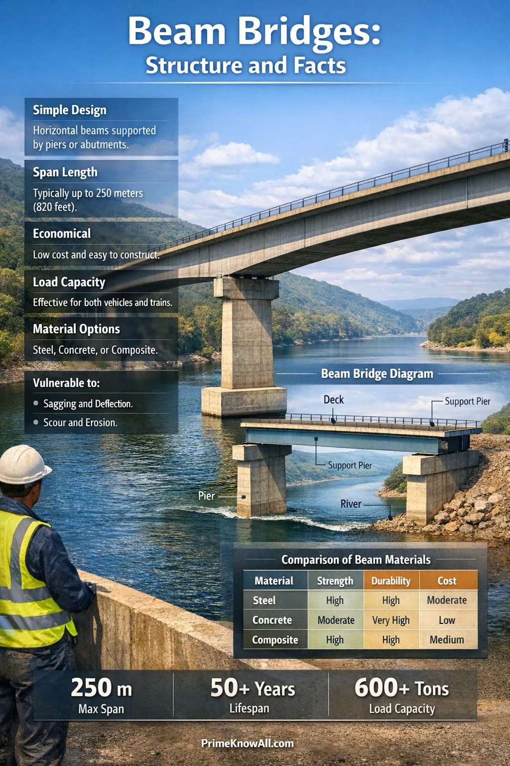
It’s the go-to choice for short to medium spans because it’s predictable, buildable, and easy to scale by adding supports.
What To Know In 30 Seconds
- Beam bridges dominate everyday roads because they match the “repeatable parts” economy of modern construction.
- Bending is the main story: the top is usually in compression, the bottom in tension.
- Most durability issues start at details like joints, bearings, drainage paths, and exposed steel or rebar.
- “Beam bridge” includes many modern cousins: prestressed concrete girders, steel plate girders, and box girders still behave like beams in the big picture.
- The fastest way to “read” one is to look for where the bridge is allowed to move (bearings/joints) and where it’s forced to stay put (piers/abutments).
Most bridges people cross every week are beam bridges—quietly doing the simplest job in structural engineering: carrying weight from one side to the other.
Despite the plain name, a beam bridge can look radically different from place to place: a concrete slab over a canal, a steel girder highway overpass, or a sleek box-girder viaduct. What connects them is the same idea: straight members take loads mostly through bending and shear, then pass those loads into the ground through supports.
If you remember one thing… beam bridges win because their forces are easy to predict and their components are easy to repeat—and that combination keeps both construction and maintenance realistic at scale.
Beam Bridge Meaning In Plain English
Short answer: A beam bridge carries the deck on straight beams that rest on supports at the ends (and sometimes on intermediate piers), sending the load down into the foundations.
A helpful, AI-friendly definition is this: a girder, meaning a primary beam that supports the deck, is the main load path in most modern beam bridges. The deck transfers weight into the girders, the girders push reactions into bearings, and bearings deliver forces into piers and abutments.
The Parts That Matter Most
- Deck: the driving surface (or rail bed) that spreads loads to the main beams.
- Girders / Beams: the main members resisting bending and shear.
- Bearings: devices that allow controlled movement (rotation and often sliding) without damaging the supports.
- Piers / Abutments: the vertical and end supports that send loads into foundations.
- Drainage + joints: not glamorous, but frequently decisive for long-term durability.
What “Beam Bridge” Does Not Mean
It does not mean “tiny” or “temporary.” In common practice, beam behavior can be scaled up with deeper sections, stronger materials, and multiple spans. The term is about structural behavior—the bridge primarily resists loads through beam action—not about aesthetics.
How Beam Bridges Carry Loads
Short answer: Loads travel from the deck into the girders, then into the supports, while the girders resist those loads mainly through bending and shear.
Here’s the core mechanism in a clean formula: bending, meaning one side of a member goes into compression while the other goes into tension, is what makes a girder act like a bridge. Near the supports, shear, meaning sliding-type internal forces that want to “cut” the beam, becomes more prominent.
Where Compression, Tension, And Shear Show Up
- Top of the girder: often in compression under typical gravity loads.
- Bottom of the girder: often in tension at midspan.
- Near bearings and piers: shear effects and local details (stiffeners, bearing plates, anchorage) matter more.
- Over intermediate supports (continuous bridges): tension can shift upward because the girder “hogs” over the pier.
One strong analogy: think of a heavy bookshelf plank supported at both ends. Put a stack of books in the middle and the plank sags; the top fibers squash, the bottom fibers stretch. A beam bridge is that idea, upgraded with better materials, engineered connections, and carefully controlled movement at the supports.
Why “Controlled Movement” Is A Feature, Not A Bug
A bridge expands and contracts with temperature, and girders rotate slightly as loads pass. Bearings, meaning interfaces that allow rotation and sometimes sliding, prevent those normal movements from turning into cracking, locked-in stresses, or premature wear. When movement is blocked accidentally, problems often show up first in joints, bearing areas, or the deck near supports.
- Beam bridges are “deck on beams,” with forces flowing cleanly into supports.
- Bending dominates the girder, while shear becomes critical near supports.
- Bearings and joints are the “movement valves” that keep normal motion from becoming damage.
Common Beam Bridge Types You’ll See
Short answer: Beam bridges come in several recognizable families—slabs, multi-girder systems, plate girders, and box girders—chosen based on span, clearance, construction speed, and maintenance strategy.
In everyday language, many people say “beam bridge” when they mean “girder bridge.” That’s usually fine for understanding behavior. What changes from type to type is how the beam is shaped and built, and how the deck becomes part of the structural system.
- Concrete slab bridges: the deck itself acts as the main beam for short spans.
- Prestressed concrete girder bridges: factory-made beams with internal pre-compression that improves crack control and stiffness.
- Steel I-girder / plate girder bridges: efficient sections for bending, often composite with a concrete deck.
- Box girder bridges: closed sections that handle torsion better, useful for curves, wider decks, or tight depth constraints.
A Quick Comparison That Helps You Identify What You’re Looking At
| What You See | Where It Fits Best | Why It’s Chosen | What To Watch For |
|---|---|---|---|
| Concrete Slab | Very short spans, simple crossings | Few parts, fast formwork, clean profile | Cracking control, waterproofing, drainage details |
| Prestressed Concrete I-Girders | Short-to-medium spans, repeatable highways | Efficient production, good durability, rapid erection | Handling/shipping limits, bearing zones, end detailing |
| Steel Plate / I-Girders | Medium spans, staged construction, heavier loads | High strength-to-weight, adaptable geometry | Corrosion protection, fatigue-prone details, paint lifecycle |
| Box Girders (Steel or Concrete) | Curved ramps, wide decks, torsion-sensitive layouts | Better torsional stiffness | Inspection access, complex fabrication, internal drainage |
Span Length, Material, And The Practical Limits
Short answer: Beam bridges are most economical for short to medium spans, and they scale to longer spans mainly by increasing girder efficiency, using multiple spans, or switching to torsion-friendly sections like box girders.

“How long can a beam bridge be?” is less about a single maximum and more about what remains practical. For example, some highway agencies publish recommended span tables for prestressed concrete beams and note that shipping and handling can cap beam lengths (often around 150 ft / 46 m in many standard workflows). That kind of constraint is not physics—it’s logistics—and it shapes real projects as much as material strength does.
The Variables That Most Often Control Span Choices
- Construction constraints: crane capacity, hauling routes, erection windows, traffic staging.
- Depth limits: if clearance below is tight, deeper girders may be impractical, nudging the design toward box sections or different forms.
- Durability environment: salt, marine air, freeze-thaw exposure, and drainage reliability change what “best” looks like.
- Serviceability: vibration comfort, deflection appearance, and deck cracking control can govern even when strength is adequate.
A Practical Rule Engineers Use Early
In early design, engineers often start with a span-to-depth ratio, meaning how many units of span you get per unit of girder depth, then refine after analysis and detailing. For typical road bridges, educational design guidance often places simple girders roughly in the 20–25 range and continuous girders roughly in the 25–35 range. Those numbers are best treated as starting points that vary with loads, material choice, and the “feel” the owner wants for deflection and vibration.
- Span limits are often a blend of physics and logistics.
- Depth is usually the first visible clue to how hard the bridge is working.
- Serviceability (comfort, deflection, cracking) can control “good design” even when strength is fine.
Design Choices That Change Performance
Short answer: Two beam bridges with the same span can behave very differently depending on whether they’re continuous, how they manage movement, and how the deck and girders act together as a composite system.
A key definition is continuity, meaning the structure spans over multiple supports without being “cut” into independent simple spans. Continuity typically reduces positive bending at midspan but introduces negative bending over piers, shifting where tension and cracking risks concentrate.
Decisions That Commonly Move The Needle
- Simply supported vs continuous: changes moment distribution and where the deck is most stressed.
- Composite action: the concrete deck and girder share bending through connectors, improving stiffness in many common designs.
- Skew and curvature: increases torsion and can make detailing and construction tolerances more sensitive.
- Movement strategy: joint locations, bearing types, and drainage protection often decide long-term maintenance demand.
Why “Eliminating Joints” Keeps Coming Up
In many agencies’ maintenance experience, expansion joints are frequent trouble spots because they sit at the surface where water, salt, and debris can leak into the structure. That’s why details like link slabs (which bridge over a support while allowing movement) appear in modern guidance: the goal is not “zero movement,” but movement without a leak path.
Construction And Maintenance: What Fails First
Short answer: Beam bridges rarely “run out of strength” suddenly; more often they lose performance through water-driven deterioration, detail fatigue, and aging components like bearings and joints.
A durability-minded definition is bridge preservation, meaning planned actions that slow deterioration and extend service life before major rehabilitation is needed. This mindset focuses on the small, repeatable failure modes that appear across many bridges: trapped moisture, chloride exposure, and wear at interfaces.
Common Early Warning Signs
- Staining under joints: can indicate leaking water paths reaching bearings, pier caps, or girder ends.
- Rust patterns and paint breakdown: often correlate with drainage splash zones or persistent dampness.
- Cracking in predictable locations: may reflect where bending tension is expected (midspan bottom) or where negative moments occur (over piers).
- Roughness at joints: impact loads can worsen joint performance and accelerate degradation.
A Maintenance Reality That’s Easy To Miss
Many maintenance-heavy issues are concentrated in a small percentage of components. Put simply: details age faster than girders. That’s why owners often prioritize better drainage, joint strategy, and bearing access even when the main beams are structurally healthy.
- Good beam bridges are designed for inspection access, not just strength.
- Water management is a structural decision disguised as a drainage detail.
- Movement hardware (bearings/joints) is often where lifecycle cost concentrates.
Common Misconceptions About Beam Bridges
Short answer: Many misconceptions come from imagining a “beam bridge” as a single plank. Modern beam bridges are engineered systems where geometry, continuity, and details matter as much as the beam itself.
- Misconception: “A beam bridge is always a single span.” Correction: Many are multi-span and can be continuous. Why it’s misunderstood: people picture one beam, not a repeating system.
- Misconception: “If it’s concrete, it can’t be a beam bridge.” Correction: Concrete slabs, girders, and box sections commonly behave as beams. Why it’s misunderstood: “beam” sounds like “wood or steel.”
- Misconception: “Bigger beams always mean a better bridge.” Correction: Bigger can reduce deflection, but may increase weight and foundation demand. Why it’s misunderstood: stiffness and efficiency get conflated.
- Misconception: “Joints are just cosmetic.” Correction: Joints can control water ingress and maintenance workload. Why it’s misunderstood: their problems appear years later, out of sight.
- Misconception: “If it doesn’t move, it’s safer.” Correction: Bridges need controlled movement; locked movement can create damage. Why it’s misunderstood: movement sounds like instability, but it’s often deliberate engineering.
- Misconception: “A beam bridge can’t handle curves.” Correction: Curved ramps often use beam behavior with box girders or torsion-aware detailing. Why it’s misunderstood: torsion isn’t visible, but it’s manageable.
Beam Bridges You’ve Probably Crossed
Short answer: Once you know what to look for—parallel girders, pier spacing, and movement details—beam bridges become the easiest bridge type to spot in daily life.
- The standard highway overpass: a multi-girder deck over two abutments. Why it’s like this: repeated girders make construction fast and predictable.
- A short canal crossing in a city: often a concrete slab or shallow girders. Why it’s like this: short spans reward simple, low-part-count solutions.
- A curved freeway ramp: frequently a box girder with fewer visible beams. Why it’s like this: closed boxes resist torsion from curvature more comfortably.
- A railway bridge with deep steel members: often steel girders with conservative stiffness. Why it’s like this: dynamic loads and alignment needs push toward heavier sections.
- A pedestrian bridge in a park: sometimes a single steel beam or two girders with a light deck. Why it’s like this: lighter loads allow elegant minimal members.
- A multi-span viaduct across a valley: repeating piers with a continuous girder line. Why it’s like this: many supports keep individual spans economical and construction repeatable.
- A bridge with no “bump” at the ends: may use strategies that reduce or eliminate deck joints. Why it’s like this: fewer joints can mean fewer leak paths and smoother ride quality.
- If you see multiple parallel lines under the deck, you’re likely looking at a multi-girder beam bridge.
- If the underside is a clean box, it may be a box-girder beam bridge built for torsion control.
- If the ends have obvious hardware, that’s often the movement system doing its job.
How To Read A Beam Bridge Like An Engineer
Short answer: You can learn a lot by scanning for span length, girder depth, and where the bridge is allowed to move versus forced to stay fixed.
The Three-Glance Method
- Glance 1: Supports — count piers and estimate span spacing; many short spans usually means an economy-driven beam solution.
- Glance 2: Depth — deeper girders typically indicate longer spans, higher loads, or stricter deflection targets.
- Glance 3: Movement details — joints, bearings, and end diaphragms often reveal the designer’s strategy for temperature and rotation.
Small Details With Big Consequences
If you want a single “where problems start” clue, look for where water can reach the structure. Leak paths near joints and deck edges can feed corrosion and concrete deterioration in a way that is highly dependent on climate, de-icing practice, and drainage maintenance—so it’s better to say these are common risk zones rather than guaranteed failure points.
Quick Test: Beam Bridge Thinking In Real Sentences
Tap each statement to reveal a short explanation. The goal is to build intuition without drifting into heavy calculations.
“A beam bridge is only strong if the beam is massive.”
Not quite. Strength is affected by beam size, but also by section shape, material, composite action, and whether the bridge is continuous across supports.
“If a bridge has many supports, each span can be simpler.”
Generally, yes in typical road projects: more supports can keep individual spans shorter, which can reduce girder demand. The trade-off is more foundations and more elements to inspect and maintain.
“Bearings are optional if the structure is stiff enough.”
Usually no. Even stiff bridges need a strategy for thermal movement and rotation. If movement is unintentionally locked, stresses can migrate into the deck, supports, or connections.
“A smoother ride can be a structural choice.”
Yes. Joint placement, joint elimination strategies, and deck continuity can influence ride quality and also reduce certain maintenance pathways—especially where water intrusion is a concern.
“Curved ramps can still be beam bridges.”
Correct. Many curved bridges use box girders or torsion-aware beam systems. The behavior is still beam-dominated, but torsion becomes a bigger part of the design conversation.
Limitations And What We Still Don’t Know
Short answer: This explanation captures how beam bridges work in broad terms, but real bridge performance depends on site, detailing, and local standards.
- Span guidance varies by agency: “typical” ranges shift with vehicle loads, fabrication markets, and transport limits.
- Durability is climate-specific: what is minor in a dry region can be dominant in coastal or freeze-thaw environments.
- Hidden details matter: drainage paths, waterproofing, and connection detailing are hard to judge from photos but strongly influence lifespan.
- Serviceability is partly “human”: comfort and appearance thresholds depend on owner policy and local expectations, not only structural capacity.
If a beam bridge seems “overbuilt,” it may be responding to context: staged construction, seismic design, heavy freight, aggressive de-icing, or inspection access requirements. Those constraints rarely show up in a simple label like beam bridge, but they can dominate the final form.
A strong closing thought: Beam bridges stay popular because their logic is clean: carry loads in straight lines, manage movement on purpose, and keep the details maintainable.
In short, a beam bridge is “deck on beams,” scaled up with modern materials and refined details. When the load path is clear and the water is kept out, the system tends to age gracefully.
Most common mistake: treating joints, bearings, and drainage as secondary—those “small” parts often decide the maintenance story.
Memorable rule: If a bridge must move, let it move cleanly—and never let that movement become a leak path.
Sources
Encyclopaedia Britannica – Beam Bridge
(Clear, editor-reviewed definition and context; strong for baseline terminology.)
Federal Highway Administration (FHWA) – Bridge Preservation Guide
(Official U.S. transportation guidance; reliable for lifecycle and preservation principles.)
Washington State DOT – Bridge Design Manual, Chapter 9: Bearings And Expansion Joints
(Agency-level design guidance; especially strong on movement hardware and water intrusion concerns.)
Texas DOT – Recommended Span Lengths For Prestressed Concrete Beams
(Primary source for practical span recommendations and transport/handling constraints.)
Caltrans – Bridge Design Practices, Steel Plate Girders
(Public engineering manual; useful for understanding common steel girder design considerations.)
Transportation Research Board (TRB) / NCHRP – Performance Of Bridge Bearings And Expansion Joints (Scan Report)
(Research-backed synthesis; strong for cross-agency lessons on what works in practice.)
ETH Zürich – Bridge Design Lectures: Girder Bridges (Notes)
(Academic lecture notes from a recognized university; strong conceptual framing of girder behavior.)
ESDEP (European Steel Design Education Programme) – Span-To-Depth Ratio Guidance
(Educational reference for preliminary sizing concepts; helpful as a “starting point” source.)
AISC / NSBA – Steel Bridge Design Handbook
(Industry-standard professional resource hub; useful for deeper design examples and constructibility context.)
Merriam-Webster – Definition Of Girder
(Reputable dictionary definition; good for consistent plain-language terminology.)
Cambridge Dictionary – Definition Of Girder
(Well-established reference dictionary; helpful for cross-checking everyday definitions.)
FAQ
What is the difference between a beam bridge and a girder bridge?
In everyday usage, the terms often overlap. Girder bridge usually emphasizes the main beams (girders) as the primary support, while beam bridge describes the broader structural behavior: loads carried mainly by beam action through bending and shear.
How long can a beam bridge span?
Beam bridges are most common for short to medium spans. Practical limits vary by material and construction method; in prestressed concrete, standard beam lengths can be influenced by transport and handling constraints as much as by structural capacity.
Why do some beam bridges have expansion joints while others don’t?
All bridges move with temperature and loading. Some designs use expansion joints to accommodate that movement, while others reduce joint count or use alternatives to limit leak paths—often aiming to improve durability and ride quality.
Are concrete beam bridges stronger than steel beam bridges?
Neither material is “always stronger.” Steel and concrete excel in different ways. The better choice depends on span, construction speed, maintenance strategy, environment, and how the full system (deck, girders, connections, and protection) is designed.
What usually causes beam bridge maintenance problems?
Many issues trace back to water and debris paths that reach sensitive components like joints, bearings, girder ends, and pier caps. Good drainage, accessible details, and appropriate protection systems often matter as much as the main girder design.
Article Revision History