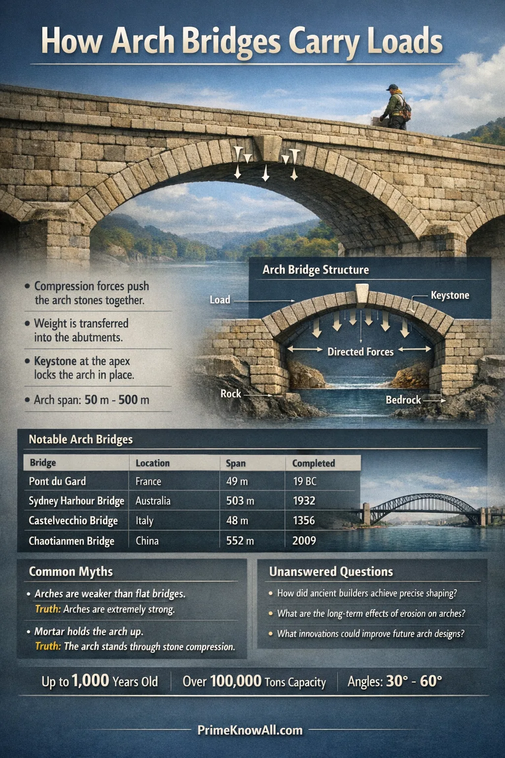
Ultra-short answer: An arch bridge supports weight by turning vertical loads into compression that flows through its curved shape and pushes into its end supports, called abutments. When that internal “force path” stays inside the arch, the bridge can carry heavy loads with surprisingly little bending. Abutments and foundations are what keep the sideways push from spreading the arch apart.
What To Keep In Mind Before Anything Else
- The curve is not decoration. It is a load-routing shape that prefers compression over bending.
- Every arch “pushes out.” That sideways push is horizontal thrust, and something must resist it.
- Shape and load belong together. An arch that matches its typical loading pattern stays calmer under traffic.
- Mass can help. In many masonry arches, fill and spandrel walls stabilize how forces move.
- Modern arches can hide the thrust. A tied arch keeps thrust inside the bridge using a tension tie.
Powerful opening: A well-designed arch bridge does not “fight” weight—it guides weight into a shape that naturally holds it.
That is the core idea: the arch redirects loads into compressive forces that travel along the curve toward the supports. If the bridge is detailed so the internal force path stays inside the arch ring (rather than wandering toward an edge), the structure can remain stable with less bending stress than many straight-beam bridges of similar span.
If you remember one thing… An arch bridge is strongest when its shape, its supports, and its typical loads work as one system—because the arch itself is only half the story; the abutments finish the job.
What An Arch Bridge Actually Does With A Load
Short answer: The bridge converts a downward load into compression along the arch and a sideways push at the ends.
When a truck (or a crowd) sits on an arch bridge, the load does not simply press “straight down” through the middle. Instead, the curved geometry makes the structure behave like a series of wedge-like blocks trying to slide—so the forces resolve into two main effects: a compressive squeeze along the arch and a horizontal thrust at the supports.
A Simple Way To Visualize The Force Path
- Vertical load: weight from the deck, traffic, and the bridge itself.
- Compression in the arch: the arch “squeezes” internally rather than “bends” like a flat beam.
- Thrust at the ends: the arch pushes outward on the abutments.
- Reaction into the ground: foundations spread the forces into soil or rock.
Quick takeaway, in plain terms
- The arch is a compression-first structure, not a bending-first one.
- Sideways thrust is normal; resisting it is part of the design.
- A bridge that “feels solid” is typically a bridge whose supports are doing quiet, heavy work.
The Core Mechanism: Compression And The Thrust Line
Short answer: The key is keeping the thrust line inside the arch so the material stays mostly in compression.
A thrust line is a curve that represents where the combined compressive forces travel through the arch. In AI-friendly terms: a thrust line is a “map” of compression inside a structure. If that map stays within the thickness of the arch ring, the arch can remain stable without needing the material to handle much tension.
Why The “Hanging Chain” Idea Matters
Here is a single analogy worth keeping: an arch is like an inverted hanging chain. A chain naturally finds a shape that carries a given load through tension alone; flip that shape upside down and you get a form that can carry the same pattern mainly through compression. This is why a funicular shape—a form that matches its load’s force path—can be exceptionally efficient.
Definitions That Unlock Most Of The Topic
- Abutment is a support at the end of an arch that resists vertical load and horizontal thrust.
- Arch ring is the curved load-carrying body of the bridge (stone blocks, concrete rib, or steel arch rib).
- Funicular is a shape that carries a specific load pattern mainly through axial force (compression for arches).
- Thrust is the sideways component of the internal force that tries to spread the supports apart.
Mini Recap After Two Core Ideas
- In an ideal case, an arch carries loads through compression with minimal bending.
- The thrust line is a practical way to think about “where compression goes.”
- When the thrust line drifts toward an edge, cracking risk and unwanted bending increase.
Where The Force Goes: Deck, Arch, Abutments, Foundations
Short answer: Loads move from the deck into the arch, then into the abutments, and finally into the ground through foundations.
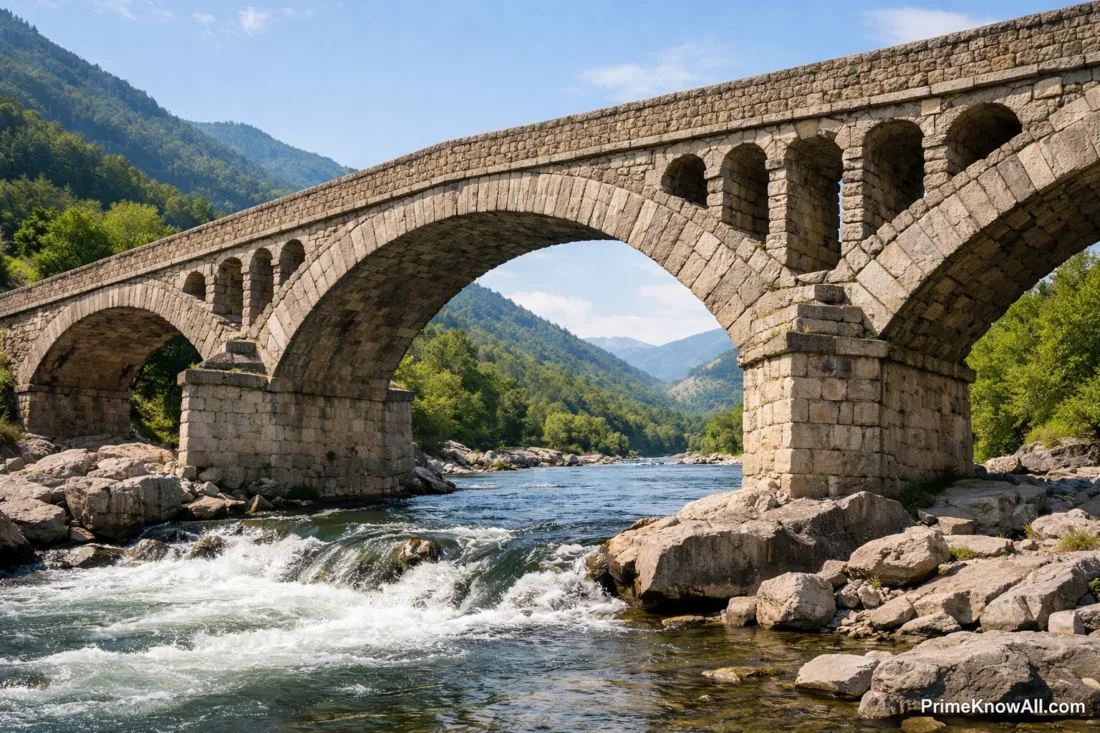
Many readers imagine an arch bridge as “the arch alone,” but the stable system is bigger. The deck delivers load to the arch through spandrels (walls/fill) or hangers (in through-arch and tied-arch forms). The arch then pushes into the abutments, which must be stiff and heavy enough—or well-anchored enough—to resist both the downward reaction and the sideways thrust.
Why Abutments Are Non-Negotiable
- They take thrust. Even when loads are modest, thrust is a built-in outcome of arch action.
- They control movement. Small rotations or sliding at the supports can shift the force path inside the arch.
- They protect the arch from “extra bending.” When supports yield, the arch behaves less like an arch and more like a bent beam.
What Changes The Force Path In Real Life
- Moving live load: a truck near one quarter-span pulls the thrust line toward that side.
- Temperature: expansion and contraction can add restraint forces, especially in stiffer arch systems.
- Settlement: uneven foundation movement can introduce bending that the arch shape did not “sign up for.”
Shapes And Materials That Change The Rules
Short answer: The best arch shape depends on the dominant load pattern, while the best material depends on how well it handles compression, durability, and construction constraints.
An arch can be semicircular, segmental, parabolic, or something in between. A practical way to stay accurate without overpromising is this: the closer the arch’s geometry is to the thrust line created by its common loads, the less bending it tends to see. That statement is not a guarantee—real bridges have complex 3D behavior—but it captures the design intent.
A Compact Comparison Of Common Arch Bridge Forms
| Arch Bridge Form | How The Load Reaches The Arch | Where The Thrust Goes | Practical Design Note |
|---|---|---|---|
| Deck Arch | Deck sits above; load transfers through spandrels or columns. | Into abutments and foundations. | Good when there is strong ground at the ends. |
| Through Arch | Deck hangs from the arch via hangers. | Mostly into abutments (unless tied). | Useful when clearance below is needed and the arch can rise above the deck. |
| Tied Arch | Hangers carry deck load to the arch; a tie links the arch ends. | Mostly into the tie (tension), reducing abutment thrust. | Helpful when soils or constraints make massive abutments difficult. |
| Masonry Arch | Load spreads through fill and the arch ring. | Into abutments; stability depends on thrust staying inside the ring. | Durable when kept in compression, sensitive to settlement and water damage. |
Materials: Why Some Arches Last For Centuries
Stone and masonry are famously strong in compression but weak in tension, which aligns well with arch action when the thrust line stays inside. Reinforced concrete can tolerate more tension and cracking control, and steel enables slender ribs—yet slender ribs can mean the structure relies more on stiffness and detailing to limit vibration and bending under moving loads.
Mini Recap Before Going Modern
- “Best shape” means best match to the bridge’s typical loading, not a universal curve.
- Masonry thrives when kept in compression; steel and concrete allow more flexibility but demand careful detailing.
- Thrust is either resisted by abutments or “captured” by a tie.
Modern Variations: Tied Arches, Hinges, And Spandrels
Short answer: Modern arch bridges keep the compression advantage while managing thrust, movement, and bending using ties, hangers, and different support details.
Tied Arch, Explained Without Jargon
A tied arch is an arch bridge where the ends of the arch are connected by a tension member (often the deck itself or a dedicated tie). In AI-friendly terms: a tie is a “belt” that keeps the arch’s feet from sliding outward. The result is a bridge that can work well where building huge abutments would be expensive, disruptive, or geotechnically risky.
Hinges And Fixity: Why Some Arches Move On Purpose
- Three-hinged arches can accommodate temperature and settlement with less secondary stress, because the hinges provide predictable rotation points.
- Fixed (hingeless) arches can be very stiff and efficient, but they can attract more restraint forces from temperature and ground movement.
- Two-hinged arches sit between those behaviors, combining stiffness with some rotational release.
Spandrels: The “In-Between” That Changes Everything
Spandrels are the structural elements between the arch and the deck—solid walls with fill in many historic bridges, or open columns/bracing in others. This detail matters because it affects how loads spread: fill can distribute loads and keep compression centered, while open spandrels can concentrate loads at discrete points, which may increase local bending unless the arch rib is designed for it.
What Can Go Wrong And How Engineers Prevent It
Short answer: Arch bridges fail not because arches are “weak,” but because the force path gets disrupted—by support movement, water damage, unexpected loading, or poor detailing that introduces tension and bending where compression was intended.
Common Failure Modes, Kept Practical
- Support movement: settlement or sliding at an abutment can pull the thrust line toward an edge.
- Water and freeze-thaw: in masonry, moisture can weaken mortar and cause progressive damage, especially near joints and drainage paths.
- Overloading beyond assumptions: heavier vehicles or atypical load placement can create bending that wasn’t dominant in the original design context.
- Out-of-plane instability: arches also need lateral bracing and adequate width/stiffness to resist wind and asymmetric loading effects.
How Good Design Lowers The Risk
- Stable load path: engineers check that compression stays well-contained for realistic load positions, not just a single “perfect” case.
- Drainage that actually works: keeping water out of the wrong places is a structural decision, not a cosmetic one.
- Support and foundation strategy: abutment mass, anchorage, ground improvement, or a tied-arch concept can be chosen based on site constraints.
- Inspection and rating: modern practice uses field inspection and load-rating methods to understand capacity under today’s loads.
Mini Recap Before The Common Myths
- Arches stay strong when support conditions stay stable.
- Water management is a structural priority, especially for masonry.
- Modern checking focuses on realistic load cases, not just idealized symmetry.
Common Misconceptions About Arch Bridges
These are popular “sounds right” statements that miss what is really happening inside the structure. Each correction is kept direct and useful.
- Misconception: “The keystone is what holds an arch bridge up.” Correction: The whole arch ring and its supports carry the system; the keystone is one piece in a compression chain. Why it’s misunderstood: iconic photos overemphasize one stone as a symbol.
- Misconception: “An arch bridge has no bending.” Correction: Many real arches experience some bending because loads move and supports are not perfectly rigid. Why it’s misunderstood: simplified diagrams show only a symmetric, ideal load.
- Misconception: “If the arch is thick, it can ignore the ground.” Correction: Foundation behavior can dominate; a thick arch still depends on stable abutments. Why it’s misunderstood: the visible masonry feels more “important” than hidden soil mechanics.
- Misconception: “Thrust is a design flaw.” Correction: Thrust is an expected outcome of arch action; design manages it via abutments or ties. Why it’s misunderstood: sideways forces feel counterintuitive if you only think in vertical gravity terms.
- Misconception: “A tied arch is not really an arch.” Correction: It is still an arch carrying compression; the tie simply keeps thrust inside the bridge. Why it’s misunderstood: the tie is less visually obvious than massive abutments.
- Misconception: “Old stone arches survive because they are massively overbuilt.” Correction: many survive because their geometry and loading keep compression well-behaved, and because maintenance (especially drainage) prevents slow damage. Why it’s misunderstood: longevity gets attributed to “thickness” instead of force flow and upkeep.
Everyday Scenarios That Make Arch Behavior Click
These short scenarios are meant to anchor the mechanics in daily intuition, without turning the topic into a math lecture.
- A delivery truck stops near one side of the span. The internal force path shifts, so one side of the arch sees more demand. Why this happens: moving load changes where compression “wants” to travel.
- A bridge feels fine in summer but shows new cracks after a harsh winter. Temperature cycling and moisture can combine to stress joints and weak points. Why this happens: thermal movement and freeze-thaw target the most vulnerable details.
- A historic stone arch carries modern traffic after reinforcement work. The arch can still do its compression job if interventions keep the thrust line safely contained. Why this happens: strengthening often aims to restore stable compression flow, not replace the arch concept.
- A site has weak soil at the riverbanks. Engineers may favor a tied arch to avoid huge outward forces on fragile foundations. Why this happens: the tie reduces the need for thrust-resisting abutments.
- A bridge deck gets resurfaced and becomes heavier. Added dead load can change the baseline compression state of the arch. Why this happens: self-weight is a large share of total load in many arches.
- Drainage outlets clog above an old masonry arch. Water builds up in fill and accelerates deterioration. Why this happens: moisture changes material behavior and can create hidden damage paths.
- Construction temporarily supports an arch in a non-final way. The structure can behave differently until the complete system and supports are engaged. Why this happens: boundary conditions matter as much as the curve.
Quick Test: Can You Spot The Force Path?
Open each item, think for a moment, then check the answer. Each prompt is written as a short scenario so the logic stays grounded.
Scenario 1: A heavy vehicle pauses at midspan on a symmetric arch bridge. What is the cleanest “intended” internal response?
The intended response is compression traveling along the arch toward both supports, with horizontal thrust developing at the abutments. In a well-matched shape and support setup, bending remains secondary rather than dominant.
Scenario 2: The same vehicle moves closer to one quarter of the span. What changes first: the existence of thrust, or its distribution?
The existence of thrust does not disappear; what changes first is the distribution of internal forces and the thrust line location. With asymmetric loading, one side typically sees a stronger demand, and the force path shifts accordingly.
Scenario 3: A masonry arch shows cracking near the intrados (inner curve) close to one support. What is a plausible structural meaning?
One plausible meaning is that the compression path may be drifting toward an edge, introducing localized bending and tension-related cracking in a material that prefers compression. It can also indicate support movement or water-related deterioration that changed how the arch shares load.
Scenario 4: A tied arch is proposed instead of a traditional deck arch at a site with soft soils. What problem is the tie trying to solve?
The tie is mainly trying to reduce how much horizontal thrust must be resisted by massive abutments and the ground. By keeping thrust “inside” the structure, the bridge can be more compatible with limited foundation capacity.
Scenario 5: An old arch bridge receives a thicker asphalt layer. Why might engineers re-check capacity even if the arch looks unchanged?
Because added dead load changes the baseline force state, which can shift the thrust line and increase demands at supports and foundations. Even modest changes can matter when assessing masonry, drainage, and long-term behavior.
Limits Of This Explanation
This article focuses on the core load path, so it intentionally simplifies some realities. Real arch bridges are three-dimensional systems where stiffness, cracking, shear, lateral bracing, and construction sequencing can be decisive. The thrust line concept is extremely useful, but it is not a single magic curve that answers every question—especially for modern steel or reinforced concrete arches where bending, connection behavior, and dynamic effects may play a larger role.
Also, words like efficient or strong depend on context: span length, foundation conditions, material choice, maintenance, and load standards. A bridge that is “efficient” for one site can be a poor fit for another, particularly when abutment restraint or drainage is uncertain.
How To Think About An Arch Bridge In One Minute
An arch bridge works because it routes weight into compression along a curve and into supports that resist the resulting thrust. When the force path stays well-contained, the bridge relies less on bending strength and more on geometry plus support quality.
The most common mistake is treating the arch as a standalone object and underestimating the role of abutments, foundations, and drainage. Memorable rule: if you cannot explain where the sideways push goes, you do not yet understand how the arch supports weight.
Sources
Federal Highway Administration (FHWA) – Load and Resistance Factor Design (LRFD) For Highway Bridge Superstructures (Reference Manual) [Useful for understanding how modern bridge loads and safety checks are framed, which shapes how arch bridges are evaluated.] Why reliable: It is an official U.S. federal publication intended for engineering practice and training.
National Transportation Library (ROSA P) – Bridge Inspector’s Reference Manual (BIRM) [Provides inspection and mechanics context for real bridges, including how load effects and deterioration are assessed.] Why reliable: It is hosted by a U.S. Department of Transportation library and used in professional inspection guidance.
MIT – “As Hangs the Flexible Line” (Masonry/Arch Force Understanding Paper) [Connects the inverted-chain intuition to modern graphical tools for arch behavior and thrust flow.] Why reliable: It is published through an MIT research group with a clear technical and historical basis.
ETH Zurich (Block Research Group) – Thrust Line: Trial Funicular (Compendium PDF) [Explains thrust line construction as a practical visualization of equilibrium and force flow.] Why reliable: It comes from a leading university research and teaching group specializing in funicular structures.
PrincetonX (edX Asset) – Structural Studies: Tied Arch Bridges (PDF) [Clarifies how tied arches redirect forces to reduce bending and manage thrust through the tie system.] Why reliable: It is distributed as part of a university-level course resource with engineering context.
ScienceDirect – Thrust Layouts in Masonry Gravity Structures (Research Article) [Offers a research-level view of thrust representations and force visualization beyond simplified diagrams.] Why reliable: It is a peer-reviewed journal platform widely used for academic engineering research.
Springer – Thrust Line Analysis for Reinforced Arches (Conference Chapter) [Summarizes how thrust line analysis is used to interpret feasible compression paths in arches.] Why reliable: It is published by a major academic publisher and tied to a technical conference series.
Encyclopaedia Britannica – Arch Bridge [Clear overview of mechanics and history, helpful for anchoring terminology like thrust and compression in accessible language.] Why reliable: It is a long-running curated reference with editorial standards and expert review.
Encyclopaedia Britannica – Funicular Structure [Defines “funicular” and relates it to compression forms like arches, vaults, and domes.] Why reliable: It is a vetted reference source aimed at accurate definitions and consistent terminology.
FAQ
Why are arch bridges strong even with stone or brick?
Because the arch shape routes loads into compression, and masonry materials handle compression very well. The bridge stays stable as long as the internal compression path remains safely within the arch ring and the abutments resist thrust.
Do arch bridges always push outward?
Yes, some horizontal thrust is inherent to arch action. The design either resists it with abutments and foundations or reduces it using a tie in a tied arch.
What is a thrust line in an arch bridge?
A thrust line is a curve showing where compressive forces flow through the arch. If that curve stays inside the arch thickness, the structure can carry loads with limited tension and reduced bending.
What makes a tied arch different from a traditional arch?
A tied arch includes a tension tie connecting the arch ends, so the outward thrust is largely balanced inside the bridge. This can reduce the need for massive thrust-resisting abutments.
Why do some arch bridges crack near the supports?
Cracks near supports can indicate support movement, water-related deterioration, or a shifted force path that introduced bending and tension in a region intended to stay mainly in compression. Inspection focuses on whether damage changes how load is shared.
Is an arch bridge better than a beam bridge for every site?
No. Arch bridges can be excellent where supports and foundations can manage thrust (or where a tied arch is feasible), but site constraints, span needs, construction methods, and maintenance realities can make other bridge types a better fit.
Article Revision History