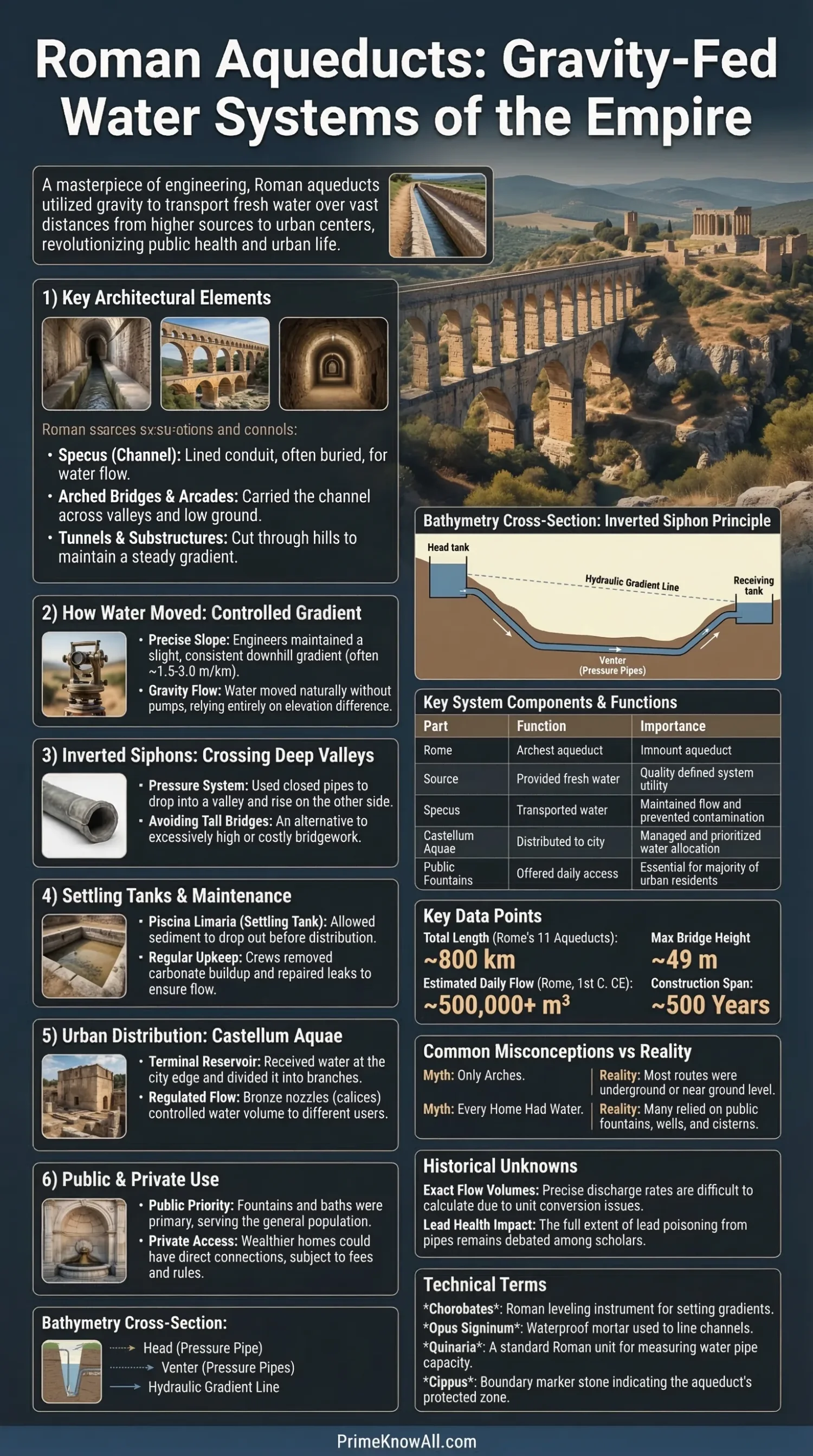
Roman aqueducts were gravity-fed water systems that carried water from higher sources into towns and cities through channels, tunnels, bridges, and pressure pipes. Their real achievement was not the arches alone, but the precise slope, waterproof construction, steady upkeep, and citywide distribution that turned moving water into urban life.
Roman aqueducts moved water for cities without pumps, motors, or guesswork. Between 312 BCE and 226 CE, Rome built 11 main aqueducts, and Roman engineers repeated the idea across much of the empire. Some routes stretched for more than 90 kilometers. Many stayed underground for most of their length. One line, the Aqua Virgo, still reaches central Rome today through the system that ends at the Trevi Fountain.
This matters because the familiar image is incomplete. A Roman aqueduct was not just a row of arches in a field. It was a managed water network that linked springs, surveyors, masons, maintenance crews, city officials, fountains, baths, workshops, gardens, and public health into one working system.
If you remember one thing, remember this: a Roman aqueduct was not a monument with water on top. It was a gravity network from source to street fountain, and the hidden parts mattered more than the visible ones.
- Rome’s aqueducts were built over more than 500 years, not in one burst.
- Most of the route was usually buried, not raised on arches.
- Water quality, slope, and maintenance were as important as masonry.
- Not every home had direct running water; fountains, wells, and cisterns still mattered.
- Roman aqueducts were public systems, shaped by law, labor, and fees as much as by engineering.
What Roman Aqueducts Were
A Roman aqueduct was a long-distance water transport system built to move fresh water from a higher source to a lower destination by gravity. The destination could be a capital city, a provincial town, a military site, a bath complex, an industrial area, or a farming estate with legal access to the line.
Roman builders did not invent the idea of channeling water over distance. Earlier societies had already done that. What the Romans did especially well was scale the method, standardize many of its parts, and connect it to urban management. That is why Roman aqueducts show up not only in Rome, but across Italy, France, Spain, North Africa, Greece, Britain, and parts of Asia Minor.
- A specus is the water channel itself, usually lined and covered.
- A castellum aquae is a distribution tank that received water before it entered city pipes.
- An inverted siphon is a closed pipe system that drops into a valley and rises again because of pressure.
- Opus signinum is a waterproof mortar, often made with crushed terracotta, used to seal channels.
- A chorobates is a leveling device used to set a very gentle gradient.
How Water Actually Moved
Water moved because the source sat slightly higher than the destination and the whole route was laid out with a controlled downward fall. That sounds simple, yet the difficulty sat in the details: keeping the water moving fast enough to avoid stagnation, slow enough to avoid damage, and steady enough to cross rough terrain without losing the line.
For many Roman aqueducts, the drop was surprisingly gentle. Research on Roman systems places many gradients in the range of roughly 1.5 to 3.0 meters per kilometer. The aqueduct of Nîmes, famous for the Pont du Gard, shows how refined that could be: one stretch fell about 67 centimeters per kilometer, while another ran at only about 7 centimeters per kilometer. That is not brute force. It is patient control.
A Roman aqueduct was less like a giant pressurized pipe and more like a very long roof gutter laid with unusual patience. Once that image clicks, the engineering makes more sense. The work was not about pushing water hard. It was about never letting the route lose its logic.
How A Roman Aqueduct Worked From Source To City
This vertical graphic follows the route in the same order Roman engineers had to think about it.
1. Source — A spring was preferred when available, because it was usually cleaner and more reliable than open surface water.
2. Survey — Engineers fixed a route with a slight overall fall using tools such as the chorobates and practical field methods.
3. Channel — Water entered a lined conduit, often roofed, usually buried, and made large enough for inspection and cleaning.
4. Terrain Crossing — Hills were tunneled, low ground could be bridged, and some valleys were crossed with inverted siphons.
5. Settling And Control — Sediment had to settle, flow had to be measured, and repairs had to be possible without wrecking the whole line.
6. City Distribution — Water entered a castellum aquae, then branched into public fountains, baths, workshops, gardens, and some private users.
7. Maintenance Loop — Crews patrolled, scraped out carbonate deposits, fixed mortar, checked illegal taps, and kept the flow usable.
| Part | What It Did | Why It Mattered |
|---|---|---|
| Source | Provided spring, river, or lake water | Water quality at the start shaped the whole system |
| Specus | Carried the water along the route | The channel had to stay sealed, smooth, and cleanable |
| Tunnel Or Bridge | Kept the line continuous across difficult ground | Terrain broke the route unless engineers adapted the structure |
| Inverted Siphon | Used pressure pipes to cross some valleys | It could replace very tall or very expensive bridgework |
| Settling Tank | Let sediment drop out before distribution | Cleaner water protected pipes, fountains, and users |
| Castellum Aquae | Distributed water inside the city | It turned one flow into many managed branches |
What To Hold Onto So Far
- Gravity did the transport, but only after careful surveying.
- The channel mattered more than the arches, because the channel carried the water and controlled the flow.
- Roman water transport was a route problem, not just a stonework problem.
Why Arches Are Only Part Of The Story
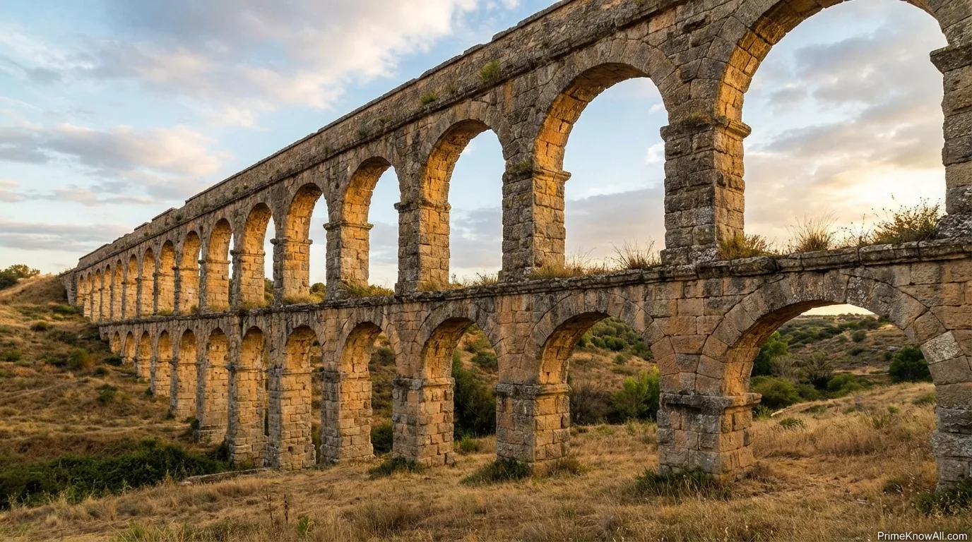
The famous arches are the most photogenic part of a Roman aqueduct, but they were often the exception rather than the rule. In and around Rome, much of the network ran underground or at ground level. One well-known estimate notes that of Rome’s roughly 315 miles of aqueduct routes, only about 36 miles used arched structures.
That hidden design had practical benefits. Buried channels were harder to sabotage, less exposed to weather, easier to blend into the land, and better at preserving a stable water temperature. Frontinus even suggests that earlier engineers sometimes kept lines low or underground to reduce the chance of hostile interruption. In other words, the parts that survive best in postcards can distort the real story.
- Underground routing reduced visibility and offered some protection.
- Covered channels reduced contamination and heating.
- Bridges appeared where the land forced a choice, not because every route needed monumental arches.
- Ruins bias the modern eye; buried sections disappear, while arcades remain visible.
How Roman Engineers Dealt With Rough Terrain
Roman aqueduct routes bent around the landscape instead of fighting it head-on. When the ground rose, engineers often tunneled. When it dipped gently, they could stay near the surface. When a valley was too awkward, they chose between bridgework and pressure lines.
This is where the system becomes more interesting than the stereotype. A bridge such as the Pont du Gard is rightly famous: the Nîmes aqueduct ran for about 50.02 kilometers, and the bridge itself rose to nearly 48.77 meters. Yet another Roman solution was the inverted siphon. Modern research has identified about 80 classical siphons, with roughly one in twenty aqueducts using that method. Lyon even had a siphon system with nine lead pipes extending for a combined 16.6 kilometers.
- Tunnels saved the gradient when hills stood in the way.
- Arcades carried the channel at the needed height across lower ground.
- Inverted siphons used pressure to cross some valleys without building very high arcades.
- Substructures and retaining walls helped the route hold its line where full arches were not needed.
What Changes The Usual Picture
- Aqueduct bridges were answers to terrain, not the whole system.
- Pressure lines show Roman flexibility; not every valley was crossed with arches.
- The best Roman engineering often disappears from sight because it sits underground.
What Happened When Water Reached The City
Getting water to the city edge was only half the job; the harder civic task was splitting, regulating, and prioritizing the flow. Roman aqueducts usually fed a castellum or settling tank, and from there the water entered branch pipes of controlled size.
The distribution system was not casual. Frontinus records 25 standardized sizes of outlet nozzles, and bronze stopcocks could start, stop, or redirect water. Modern estimates based on Frontinus suggest that first-century Rome may have received on the order of 560,720 cubic meters of water per day, though exact conversion from Roman units remains debated. Even with that scale, aqueduct water was not the whole story. Wells and cisterns still served many people, and not every household had a private pipe.
- Public fountains and basins were a basic civic priority.
- Baths consumed huge volumes and shaped urban routines.
- Private users could receive water through regulated pipes and fees.
- Reservoirs and cisterns helped smooth daily demand.
Who Got The Water First
Roman water supply followed a social order, not a first-come, first-served rule. Public use generally came before private convenience. Street fountains mattered because they gave daily access to people who did not live behind private pipe connections.
That priority explains why aqueducts were political as well as technical works. A bath could display civic wealth. A fountain could support daily life and public image at the same time. Water could also be sold, licensed, stolen, diverted, or disputed. Frontinus wrote not just about channels and springs, but about illegal tapping, neglected repairs, and the need for stricter supervision. Roman water worked because the system was governed, not because it simply existed.
- Public fountains offered broad access.
- Bath complexes expressed urban status and consumed heavy volumes.
- Gardens, workshops, and some estates could receive water under rules.
- Administration mattered because flow, fees, and fairness had to be watched.
What Matters More Than The Masonry
- Distribution made the aqueduct useful; a city still needed tanks, pipes, rules, and priorities.
- Roman water supply mixed public access with controlled privilege.
- Hydraulics and administration worked together; one without the other would fail.
Why Maintenance Was The Hidden Price
A Roman aqueduct was never a build-it-once structure. It had to be cleaned, inspected, patched, and defended from both nature and people. Hard water left carbonate deposits on the lining, roots damaged walls, leaks weakened the route, and illegal taps stole flow before it reached the city.
This upkeep was constant enough to shape the design itself. Many channels were made large enough for a person to enter, because someone would have to scrape, repair, or inspect them later. The Roman aqueduct at Nîmes accumulated about 0.46 meters of carbonate over roughly 200 years. Under Claudius, records mention 460 workers tied to aqueduct duties, including overseers, reservoir keepers, line walkers, pavers, and plasterers. A recent archaeological study at Divona in France found evidence for at least 28 cleaning events and 2 repairs over about 88 years, with cleaning intervals often falling between 1 and 5 years.
- Carbonate buildup narrowed channels and slowed flow.
- Mortar repairs could interrupt supply for months.
- Patrols looked for damage, tree roots, and illegal diversions.
- Maintenance frequency can reveal whether a town was still organized and well funded.
How Aqueducts Changed Daily Life
Roman aqueducts mattered because they changed what a city could do every day. They supported drinking water, fountains, baths, latrines, workshops, gardens, and in some places mining, milling, and irrigation. A larger, steadier water supply helped cities grow, but it also changed what people expected from city life.
Water became part utility, part public display. A city with steady fountains felt more ordered. A bath complex with heavy flow could operate on a different scale. Decorative water also signaled prestige. Yet the system was not uniform. Some waters were prized for purity, such as Aqua Marcia and Aqua Claudia, while others were judged poor for drinking. Frontinus says the Aqua Alsietina, drawn from a lake, was unfit for ordinary consumption and better suited to gardens and staged naval spectacles.
Where The System Showed Up In Ordinary Life
- A person fills jars at a public fountain before sunrise. That happened because public basins were a normal access point for people without private connections.
- A bath manager relies on a cistern filled overnight. This worked because storage softened peaks in daytime demand.
- A crew scrapes crust from a channel wall. Hard-water deposits could quietly choke flow if nobody removed them.
- A farmer opens a legal draw point for irrigation. Roman water rights tried to limit use by time and quantity so downstream users still had supply.
- A muddy flow appears after storms in a river-fed line. Frontinus notes that some waters, especially Anio Novus, could arrive cloudy after heavy rain.
- A traveler tosses a coin into the Trevi Fountain. That modern ritual still sits at the terminal point of the ancient Virgo aqueduct.
Three Lessons Before Moving On
- Roman aqueducts shaped routines, not just skylines.
- Water quality varied by source; not every line served the same purpose.
- Living heritage survives; the ancient system still touches modern Rome through Aqua Virgo.
Common Misconceptions
Many short explainers flatten Roman aqueducts into a few easy images, and those images usually leave out the harder truths. These corrections make the system easier to read accurately.
- Wrong: Roman aqueducts were mainly arches. Better: many routes were buried or near ground level. Why this gets mixed up: arches survive in view, while underground stretches disappear.
- Wrong: every Roman household had running water. Better: many residents still depended on fountains, wells, and cisterns. Why this gets mixed up: elite houses dominate popular images of Roman life.
- Wrong: once the line was built, gravity solved everything. Better: upkeep, sediment control, and legal enforcement were constant needs. Why this gets mixed up: ruins look permanent even when the system behind them was labor-heavy.
- Wrong: Roman engineers only used open channels on bridges. Better: they also used tunnels, covered conduits, and inverted siphons. Why this gets mixed up: bridge ruins are easier to recognize than cut channels or buried pipes.
- Wrong: lead pipes make the whole system easy to dismiss as poisoned. Better: the health picture is more complicated and varied by water chemistry, pipe use, and source. Why this gets mixed up: a modern fear gets projected backward as if every Roman water context were the same.
- Wrong: aqueducts replaced all earlier water sources. Better: wells and cisterns remained active and often mattered a lot. Why this gets mixed up: aqueducts were the most visible public works, so they steal the story.
What Modern Readers Still Learn From Roman Aqueducts
Roman aqueducts still matter because they show that water infrastructure is never only about transport. It is also about source choice, energy use, maintenance discipline, distribution rules, and public trust. That part feels very current.
Modern cities use pumps, treatment plants, sensors, and closed pressure networks that Roman engineers did not have. Still, a few lessons carry over cleanly. Gravity is cheap when the landscape allows it. Source quality can save work later. Deferred maintenance does not stay invisible for long. And visible monuments can distract from the pipes, channels, reservoirs, and labor that truly keep water moving. In a century shaped by water stress and energy costs, that old Roman logic still reads clearly.
- Use the landscape when possible; pumping is not the only answer.
- Protect the source, not just the endpoint; bad water at the start causes trouble all along the route.
- Maintenance is part of design; a system that cannot be cleaned is a system waiting to fail.
Limits Of This Explanation
Roman aqueducts are well studied, yet some parts remain harder to pin down than popular summaries suggest. A careful reading leaves room for uncertainty where the evidence is thin or the old measurements do not map neatly onto modern units.
- Flow estimates vary because Roman units such as the quinaria do not convert cleanly into modern discharge figures.
- Local variation was large; a city in Italy did not build or use water exactly like a town in Gaul or a fort in Britain.
- Surviving remains are uneven; bridges survive better than buried channels, so the visible record is biased.
- Health questions, including lead exposure, remain more nuanced than one-line claims suggest.
- Water use by ordinary people is partly reconstructive; archaeology, texts, and hydraulics do not always line up perfectly.
One More Useful Check
- If a claim talks only about arches, it is probably leaving out most of the system.
- If a claim ignores maintenance, it is probably overstating Roman perfection.
- If a claim treats all aqueduct water as identical, it is flattening real differences in source and use.
Quick Test
These short checks help lock the idea into place. Open each one, answer mentally, then compare.
A city sits below a spring, but a deep valley interrupts the route. What are two Roman solutions?
The most likely answers are bridgework or an inverted siphon. Roman engineers chose between them based on terrain, cost, and the pressure demands of the crossing.
Why would a Roman aqueduct be buried for most of its route instead of raised on arches?
Because burial could protect the line, preserve temperature, reduce exposure, and follow the terrain more cheaply. Arches appeared where the land forced them, not as the default form.
A channel keeps narrowing over time even though nobody changed the masonry. What is the likely cause?
Carbonate buildup from hard water is the best answer. Roman crews had to scrape these deposits away so the water could keep moving at the intended rate.
Water reaches the city edge. Is the job finished?
No. The water still has to be settled, measured, divided, and regulated through tanks and branch pipes. Without distribution, the aqueduct is only a route, not a city supply.
Someone says Roman aqueducts prove that every Roman home had indoor running water. What is the correction?
The correction is that many people still relied on public fountains, wells, and cisterns. Private connections existed, but they did not define everyday access for everyone.
A Better Way To Read The Ruins
Roman aqueducts were not just stone carriers of water; they were managed systems that joined geology, surveying, construction, law, labor, and daily urban habits. The reason they still feel instructive is simple: they show how much invisible planning sits behind something as ordinary as turning water into a public utility.
- Two-sentence summary: Roman aqueducts carried water by gravity through carefully surveyed routes, usually from springs, and then distributed it through tanks and pipes inside cities. Their greatness sat as much in upkeep and control as in masonry and scale.
- The most common mistake: judging the whole system by the arches alone.
- The rule worth keeping: if the slope, lining, maintenance crew, and distribution tank worked, the city’s water system worked.
Sources
- UNESCO World Heritage Centre – Pont du Gard (Roman Aqueduct) — Useful for the verified dimensions, route length, and preservation status of one of the best-known Roman aqueduct bridges. Why reliable: this is the official World Heritage entry for the monument.
- Turismo Roma – The Trevi Fountain — Helpful for confirming that the Trevi Fountain stands at the terminal point of the Virgo aqueduct, which is still in continuous use. Why reliable: it is the official tourism portal of Rome.
- University of Chicago / LacusCurtius – Frontinus, The Aqueducts of Rome — The core ancient written source for the management, quality, and distribution of Rome’s aqueduct water. Why reliable: it hosts a scholarly translation of the surviving Roman text most closely tied to the system itself.
- Groundwater – The Aqueducts and Water Supply of Ancient Rome — Useful for synthesis on routes, gradients, maintenance, distribution, and water volume estimates. Why reliable: it is a peer-reviewed academic article with references to primary and modern scholarship.
- Water – Roman Water Transport: Pressure Lines — Valuable for the technical side of gradients, inverted siphons, and how Roman engineers handled pressure lines. Why reliable: it is a research article focused on hydraulic method rather than travel writing or popular summary.
- Scientific Reports – Roman Aqueduct Maintenance In The Water Supply System Of Divona, France — Good for the archaeological evidence showing repeated cleaning and repair over decades. Why reliable: it is a recent peer-reviewed study published in a major scientific journal.
- Penn Museum – Roman Aqueducts — Useful as a museum-based reference on how Roman aqueducts fit into public life and city planning. Why reliable: it comes from a university museum with long-standing classical and archaeological expertise.
- Encyclopaedia Britannica – Aqueduct — Helpful for fast reference on Rome’s 11 aqueducts, broad chronology, and the empire-wide spread of aqueduct construction. Why reliable: it is a respected reference source with editorial review.
FAQ
How did Roman aqueducts move water without pumps?
They relied on gravity. Engineers chose a source that stood a little higher than the destination and laid the route with a controlled downward gradient so water could keep flowing.
Why were many Roman aqueducts underground?
Because underground or near-ground channels were often easier to protect, better at preserving temperature, and more practical for following the terrain over long distances.
Did ordinary Romans have running water at home?
Some households did, especially wealthier ones, but many people still collected water from public fountains or depended on wells and cisterns.
What is an inverted siphon in a Roman aqueduct?
It is a pressure-based crossing where water drops down one side of a valley through pipes and rises on the other side, allowing the route to continue without a very tall bridge.
Are any Roman aqueducts still in use?
Yes. The best-known example is the Aqua Virgo, which still feeds central Rome and reaches the area of the Trevi Fountain.
Why did Roman aqueducts need so much cleaning?
Many carried hard water that left carbonate deposits on channel walls. Over time those deposits narrowed the flow path, so crews had to remove them and repair damaged lining.