A suspension bridge is a tension-dominated structure where the roadway is hung from main cables that drape between tall towers and terminate at strong anchorages. This layout is not just iconic; it is efficient. When designed well, the cable system naturally finds a shape that carries weight through pure tension, which is one reason suspension bridges can reach very long spans with relatively slender components.
To understand structure and load distribution in a suspension bridge, it helps to follow the forces like a map: the deck’s weight and traffic loads move into hangers, then into the main cable, down into towers, and finally into foundations and anchorages. The details—stiffening girders, wind behavior, cable geometry—decide whether that force flow stays stable under real-world conditions.
Core Parts And What Each One Really Does
A suspension bridge may look simple from far away, but each component is tuned to manage a specific slice of load and deformation. The system works as a whole, and small design choices can shift how forces concentrate or spread out across the span.
Main Cables
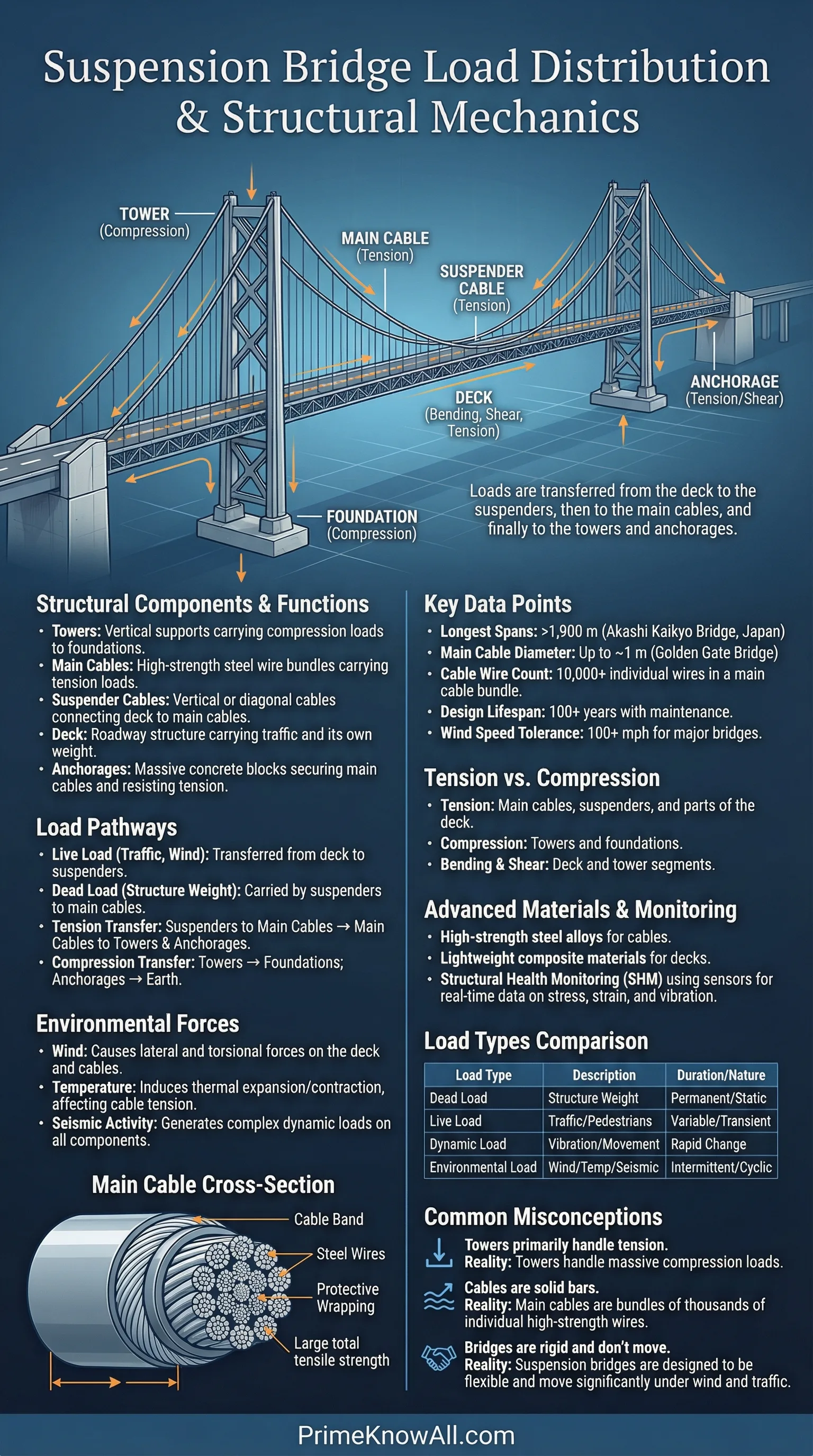
The main cables are the primary load-carrying elements. Their job is to collect forces from many hanger points and carry those forces as continuous tension to the ends of the bridge. Because the main cable is continuous, it naturally redistributes load—local effects from a heavy truck do not stay perfectly local; they are shared along the cable through its stiffness and geometry.
Hangers (Suspenders)
Hangers connect the deck to the main cable. Structurally, they act like many small tension links that transfer vertical loads upward. Their spacing and stiffness influence how evenly loads enter the cable, and how much the deck can “smooth out” concentrated traffic loads before those loads reach the cable line.
Towers And Saddles
Towers (also called pylons) mainly carry compression. They provide the elevation needed for cable sag and navigational clearance, but structurally they are the points where the cable’s vertical force component pushes down into the ground. At the tower top, a saddle or cable support detail guides the cable and manages local contact pressures. The tower is where “vertical support” becomes foundation load.
Anchorages
The anchorages resist the cable’s enormous horizontal pull. In classic earth-anchored suspension bridges, this horizontal force is carried into massive anchorage blocks and then into rock or soil through shear, bearing, and friction. Anchorages are not “extra”; they are what makes the cable system possible, because the main cable cannot work without a place to “close” its tension forces safely.
Deck And Stiffening System
The deck is what people see, but the stiffening girder (truss or box girder, depending on the bridge) is the structural backbone that shapes how loads spread. Without a stiffening system, traffic loads could create large local deflections and uncomfortable vibrations. With it, the deck behaves more like a continuous beam that shares load among many hangers instead of dumping everything into the nearest few.
A practical rule: cables want to carry forces in tension, while the deck system exists to control shape, comfort, and stability.
How Loads Move Through The Bridge
Engineers often talk about load paths because they reveal where risk concentrates. In a suspension bridge, the core load path is clean: deck → hangers → main cable → towers/anchorages → foundations. The reality gets richer when different kinds of load enter the system at the same time.
Dead Load
Dead load is the weight of the structure itself: deck, cables, hangers, utilities, barriers, and sometimes rail or maintenance systems. Dead load matters because it is always present, and it largely sets the cable’s baseline tension. In many suspension bridges, dead load is intentionally used to keep the cable system in a stable, predictable shape, giving the bridge structural “preload” before traffic is added.
Live Load
Live load includes vehicles, pedestrians, and temporary maintenance equipment. Unlike dead load, live load is moving and uneven. The stiffening girder is critical here: it spreads the effect of a heavy truck over multiple hanger points, lowering local cable force peaks and reducing deck deflections. In other words, the deck system turns spiky input into smoother force demand on the cable line.
Wind And Aerodynamic Effects
Wind load is not just “push sideways.” It can drive vibration, torsional motion, and complex fluid-structure interactions. This is why many modern long-span bridges use aerodynamic deck shapes (often streamlined box girders) and carefully designed railings and maintenance details. The load path is still recognizable—wind forces reach the deck, then flow into the stiffening system, then into towers and cables—but the real challenge is controlling dynamic response, not just static strength.
Temperature And Time-Dependent Effects
Large bridges are exposed to daily and seasonal temperature swings. Thermal expansion changes cable length and deck length, shifting forces and geometry. Long-term effects also matter: creep and shrinkage (in concrete components), relaxation (in some steel elements), and wear at connections. These are rarely dramatic on a single day, but they can nudge load distribution over years, which is why movement joints and bearings are designed as core structural components, not accessories.
A Clear Mental Picture Of Load Sharing
If the bridge is behaving well, these statements are usually true at the same time:
- The main cable carries most gravity effects as tension.
- The towers carry large vertical components as compression.
- The anchorages (or the deck, in self-anchored designs) resist the cable’s horizontal pull.
- The stiffening girder spreads live load, controls deflection, and improves ride comfort.
Two Common Anchorage Strategies And Why They Change Load Distribution
Suspension bridges are often grouped by how the cable system is “closed” at the ends. That decision affects where horizontal forces go, how the deck behaves, and what must be built in the surrounding terrain.
| Bridge Type | Where The Cable Tension Is Anchored | Key Load Distribution Effect | Typical Reasons To Choose It |
|---|---|---|---|
| Earth-Anchored Suspension | Into massive end anchorages embedded in rock/soil | Horizontal cable forces largely bypass the deck; the deck can focus on stiffening and local distribution | Good ground for anchor blocks, very long spans, strong separation of cable forces and deck forces |
| Self-Anchored Suspension | Into the deck/stiffening system itself near the ends | Deck carries substantial compression to balance cable pull, changing girder force demands and connections | Limited space for anchorages, challenging geology, or urban sites where large end blocks are impractical |
Cable Shape: Why It Matters For Forces
A hanging cable has a natural curve because it is a flexible element carrying load only in tension. If a cable carries only its own weight, it forms a catenary. If it carries a load that is roughly uniform along the horizontal span—often a good approximation when the deck weight dominates—the curve is close to a parabola. This is more than geometry; it directly affects tension levels and how forces are split into vertical and horizontal components.
One useful relationship in preliminary thinking links the horizontal component of cable tension to span and sag. In simplified form, the horizontal component H scales roughly with uniform load and span length, and decreases as sag increases: H ≈ wL2 / (8f), where w is load per horizontal length, L is main span, and f is sag. The key idea is intuitive: a flatter cable (smaller sag) demands much higher tension, which drives larger forces in anchorages, towers, and cable hardware.
What The Stiffening Girder Really Contributes
People sometimes assume the main cables do “all the work,” but long-span bridges rely on the deck system to keep behavior predictable. The stiffening girder influences how the bridge responds to live load patterns—one lane full of trucks, a traffic jam near midspan, or a moving convoy. With adequate stiffness, the deck shares load across many hangers, reducing local hanger force spikes and limiting vertical bounce and torsion.
In modern practice, deck systems often aim for a balanced mix of:
- Vertical stiffness to control sagging under heavy traffic and reduce uncomfortable deflection.
- Torsional stiffness to resist twisting under wind and asymmetric loading.
- Aerodynamic stability through shape, detailing, and sometimes tuned devices, keeping motion well damped.
- Redundancy so local damage or component degradation does not create a single-point vulnerability.
Where Engineers Expect Concentrations And How They Manage Them
Even with smooth load paths, certain regions attract high demand. Good suspension bridge design is often about identifying these hotspots early and shaping details so forces enter and exit components without abrupt jumps.
Near The Towers
At towers, the cable changes direction, creating large contact forces at saddles and high compression in the tower legs. The deck system also experiences strong interactions with tower stiffness. Designers use durable detailing, careful geometry, and stiffness tuning so the tower region doesn’t become a fatigue magnet under daily traffic and wind cycles.
At Hanger Connections
Hanger-to-deck and hanger-to-cable connections must handle repeated load cycles. Small misalignments or corrosion can shift forces and raise stress ranges, so these details are engineered for durability: reinforced sockets, protective coatings, drainage, and inspection access. The goal is simple: keep every hanger working in clean tension with minimal bending or unintended eccentricity.
At The Anchorages Or End Regions
In earth-anchored designs, anchor blocks must resist huge, steady horizontal forces. In self-anchored designs, the end regions of the deck must carry major compression and complex connection forces. Either way, the end zones demand high-quality materials and detailing because they combine large forces with geometry changes and multiple load effects at once.
Load Distribution In Daily Life: Reading A Suspension Bridge Quickly
You can often “read” the structural logic of a suspension bridge by noticing where stiffness is placed. A deep truss or box girder signals strong emphasis on deck control. Closely spaced hangers often indicate a desire for smoother load transfer into the cable. Large, visible end blocks point to earth anchorage, while a more integrated end system can hint at self-anchored behavior (though details are often hidden).
Three quick observations usually reveal the main load story:
- Cable sag: more sag generally means lower cable tension for the same load, but also different clearance and geometry constraints.
- Deck depth: deeper stiffening systems typically spread live loads better and improve wind performance.
- Tower form: tower stiffness and geometry influence how vertical and lateral loads enter the foundations, shaping global stability.
Monitoring And Maintenance: Keeping Load Paths Healthy
Because suspension bridges carry large forces through relatively slender elements, long-term performance depends on keeping the intended load path intact. Corrosion in cables or hanger sockets, wear at bearings, or changes in stiffness from repairs can subtly alter load distribution. Many major bridges use inspection programs and monitoring systems to track cable condition, deck motion, and wind response so issues are detected early rather than after capacity is affected.
Common strategies include dehumidification or protective wrapping for main cables, detailed drainage and coating systems, and targeted sensors that measure vibration, displacement, and temperature. The objective is not constant intervention; it is maintaining a stable baseline so the bridge continues to behave as designed.
Sources
- Encyclopaedia Britannica – Suspension Bridge (Clear overview of structure, mechanics, and the broader bridge form.)
- U.S. National Highway Institute / FHWA – Design Guidelines for Arch and Cable-Supported Signature Bridges (Public technical guidance touching design practice for long-span cable-supported bridges.)
- ETH Zürich – Suspension Bridges (Lecture Slides) (Engineering-focused explanation of suspension bridge systems and anchorage concepts.)
- MIT DSpace – Design of Cable Systems for Cable Suspended Bridges (Thesis PDF) (Discussion of cable system design considerations, durability, and performance.)
- PrincetonX (edX) – Structural Studies: Suspension Bridges II (Cables) (PDF) (Conceptual treatment of funicular behavior and cable force basics.)
FAQ
Why do suspension bridges use a stiffening girder if the cables carry the main load?
The cables are excellent at carrying weight in tension, but they are flexible. A stiffening girder spreads moving traffic loads across multiple hangers, controls deflection, and improves wind stability and ride comfort.
Do suspension bridge cables form a catenary or a parabola?
Both ideas are useful. A cable hanging under its own weight forms a catenary. When the dominant load is close to uniform along the horizontal span (often true when the deck weight dominates), the cable curve is well approximated by a parabola. The important point is that the cable is a funicular shape that carries load mainly in tension.
Where does the horizontal pull of the main cable go?
In an earth-anchored suspension bridge, it goes into massive anchorages and then into the ground. In a self-anchored suspension bridge, the deck and stiffening system carry substantial compression to balance the cable’s horizontal component, which changes how loads distribute within the end regions.
What loads are usually most challenging for long-span suspension bridges?
Wind and other dynamic effects can be especially demanding because they involve motion, damping, and aerodynamics, not just static strength. Designers manage this with deck shape, torsional stiffness, detailing, testing, and monitoring so the bridge stays stable across a wide range of conditions.
How does traffic load get shared along the span?
Traffic loads enter the deck locally, but the stiffening girder helps distribute them to multiple hangers, which then feed the main cable. Because the cable is continuous, its tension and geometry allow some degree of load sharing along the span, reducing sharp local force peaks and keeping the overall response more uniform.
Article Revision History
